tnxTower Overview
Complete Standards Support
The program analyzes towers using the ANSI/TIA-222-I Standard or any of the previous TIA/EIA Standards back to RS-222 (1959). Steel design is checked using the TIA/EIA Standards, AISC ASD 9th Edition or the AISC LRFD Specifications, as applicable. The Canadian Standard CSA S37-01 is available as well.
Powerful Analysis & Design
tnxTower's rapid model creation tools, 3-D frame-truss models and automatic wind force and ice loading generation capabilities are just a few of the features that make this industry-standard software the premier choice for all types of communication towers.
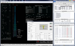
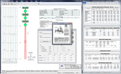
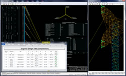
Top-notch Graphical Presentation
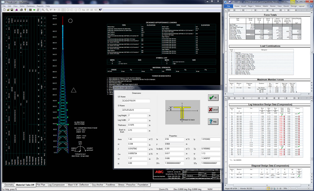
Graphical display of tower geometry, appurtenances, internal forces, stresses and displacements are created automatically.
Extensive graphics plots include material take-off, shear-moment, leg compression, displacement, twist, feed line, guy anchor and stress plots. tnxTower contains unique features such as True Cable behavior, hog rod take-up, foundation stiffness and much more.
Self-supporting tower
|
Monopole
|
Guyed tower
|
Guyed tower with candelabra
|
Specifications
tnxTower is a general-purpose modeling, analysis, and design program created specifically for communications towers.
The following Standards are currently implemented:
RS-222, RS-222-A, RS-222-B, EIA-222-C, EIA-222-D, EIA-222-E, TIA/EIA-222-F, ANSI/TIA-222-G (including TIA-222-G-1 and TIA-222-G-2),
ANSI/TIA-222-H, ANSI/TIA-222-I, and CSA S37-01.
Base Tower Types Supported
- Three or four sided guyed towers
- Three or four sided self-supporting towers
- Ground mounted monopoles (round stepped, round tapered, 18-, 16-, 12-, and 8-sided)
- Three or four sided guyed monopoles
Upper Antenna Types Supported
- Three or four sided latticed poles
- Tubular poles (round stepped, round tapered, 18-, 16-, 12-, and 8-sided)
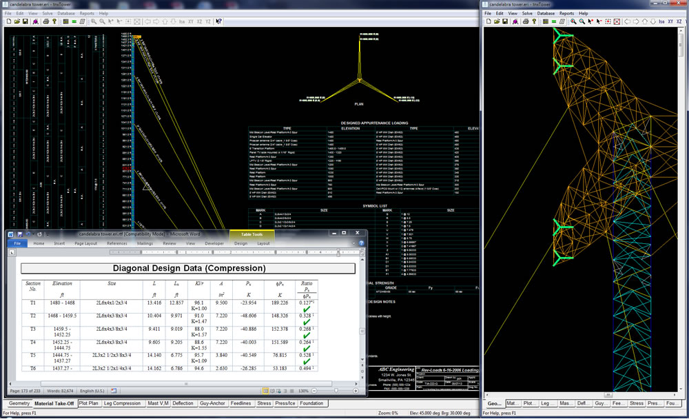
- Candelabra tops
Analysis and Design
- Automatic generation of nodes and elements for 3D frame-truss, truss, or beam-column tower models
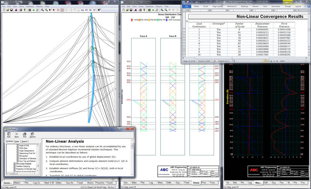
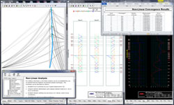
- Linear and non-linear (P-delta, cable behavior) finite element analysis (FEA)
- Three modes available: analysis only, analysis and members check, or analysis and lowest weight-optimized design
- Automatic determination of pressure coefficients, wind pressures, ice loads and resulting forces on the tower
- Optimized feed line Effective Projected Area calculations to minimize required wind loading
- Automatic calculation of feed lines shielding
- Calculation of center of pressure due to offset feed lines
- Automatic calculation of K-factors for solid round and single angle members
- Optional inner feed line support tower
- Check or design of bolts in tower members
- Export to RISA-3D for additional analysis and design options
Data Entry
- Powerful, easy to use spreadsheets for quick model generation and input verification
- Adaptable three-level structure definition: base tower, upper antenna structure, and top antenna pole
- Guy cables generation with varying radii and guy anchor elevations
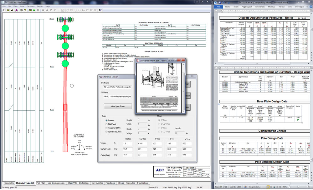
- Feed lines, discrete loads (loads from antennas, mounts, and other appurtenances), dishes, and user defined loads specification anywhere on the tower
- Comprehensive databases of structural shapes, assemblies, feed lines, dishes, antennas, mounts, and other appurtenances
- Powerful Database Manager, allowing full customization and synchronization across networks
- Flexible selection of units: US Customary (decimal or architectural notation) or SI Metric, with user-controlled display precision
Graphical User Interface
- Tabbed, dynamically updated display pages provide instant input verification for structural components and appurtenances
- Tower geometry page with zoom, pan and rotate model capabilities
- The structure may be viewed in both unloaded and deflected shape
- Individual member properties such as shape and element number can be displayed
- Material list page showing member sizes, weights, and graphical display of tower sections with reactions and tables of user defined components. User notes may also be added to this view
- Plot plan page showing boundary of tower and acreage required for 15' clearance
- Leg compression plots also displaying the leg compression and tension capacity of the tower
- Mast shear and moment plots
- Detailed tower deflection, tilt and twist diagrams
- Guy anchor plots showing guy forces and guy anchor reactions (for guyed towers only)
- Feed line plot. Displays feed lines in each of the faces of the tower
- Stress plot. Graphically displays the stress condition of members in each face of the tower
- Wind pressure and ice thickness diagrams
- Base plate and anchor bolts views (monopoles only)
Results Output
- Extensive, customizable output reports, viewable directly in Microsoft Word or Microsoft Word Viewer
- Finite Element Analysis results for detailed solution diagnostics
- Input data and results in XML format for machine processing
- DXF export of model geometry
Sample Output
To view a sample output created by tnxTower, please select from the list below:
Guyed Tower
Free-Standing Tower
Monopole
Output Verification - Hand Calculations
Hand Verification - Self-Supporting Tower TIA-222-G
Hand Verification - Self-Supporting Tower 222-F
Hand Verification - Self-Supporting Tower 222-B, C
Hand Verification - Monopole